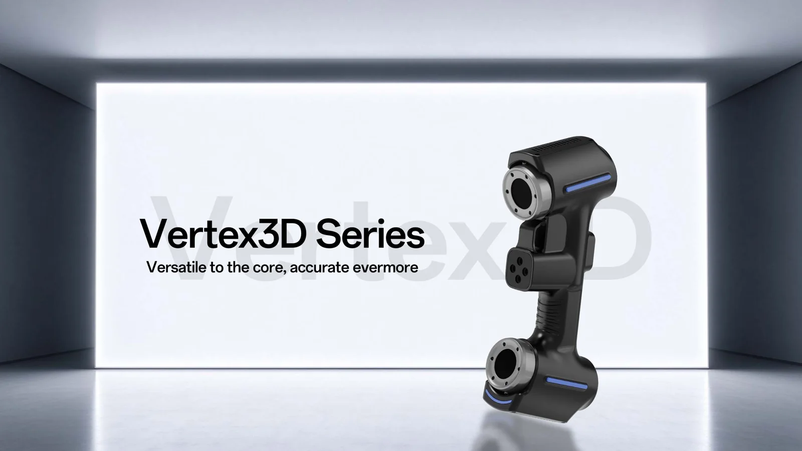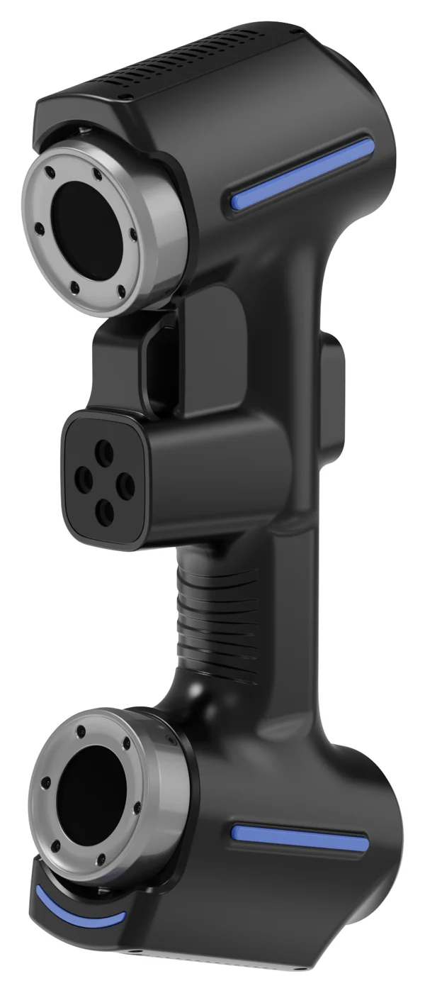
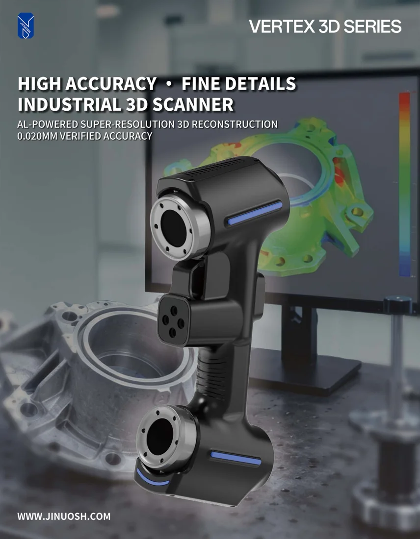
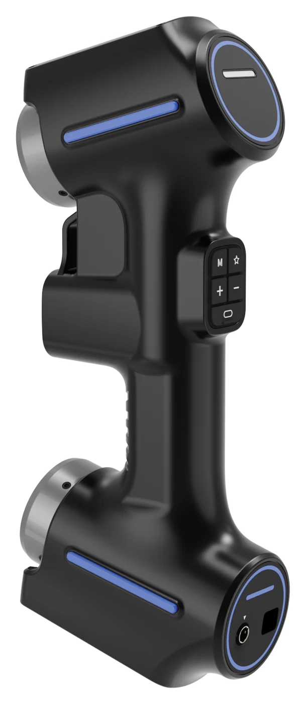
You can 3D scan shiny, reflective and dark parts by controlling three things: the surface, the geometry and the scanner settings. A light, removable matte spray fixes the surface only when it is needed. Reflective markers on and around the part, and scan angles that avoid direct glare, fix the geometry. Scanner settings, where the software offers them, help with the rest. Our JINUOSH Vertex3D and Vertex3D Pro scan shiny and polished steel, so spray is not always needed. VShark Solutions is a distributor of JINUOSH Vertex scanners and scans from Coimbatore, with the UAE as a service area.
Last reviewed: November 2026
This page is a how-to for difficult surfaces. For what the accuracy numbers mean, read handheld 3D scanner accuracy and how accurate is 3D scanning.
Why are shiny and dark parts hard to scan?
A scanner works by reading the laser light that comes back from the part. Three surface types disturb that signal:
- Shiny and mirror-like surfaces (polished steel, chrome, machined faces) throw the light away like a mirror, so the camera sees nothing at one angle and a glare spot at another.
- Dark and black surfaces absorb light, so the return is weak and the scan comes out thin or noisy.
- Transparent and translucent surfaces (glass, clear plastic) let the light pass through or scatter inside, so the surface position is wrong or missing.
The result on screen is holes, noise, spikes or a surface that looks rough when the part is smooth. The fixes below are ordered from the lightest to the heaviest.
Step 1: Try the scanner first, before any spray
Start without spray. Our Vertex3D and Vertex3D Pro scan shiny and polished steel directly, so shiny and polished steel on these two scanners needs no spray. Run a short test scan on the shiniest face and look at the live view for holes or noise. If the face comes in cleanly, carry on.
Step 2: Change the angle before you change the part
Most glare problems are about the angle between the laser, the camera and the surface.
- Tilt the scanner slightly so the mirror reflection does not point straight back at the camera.
- Avoid scanning a flat, polished face square-on from directly above.
- Scan curved and flat shiny faces from two or three slightly different directions and let the software merge the passes.
- Keep the scanner at its recommended working distance. The maker lists a 300 mm reference distance for the Vertex3D and Vertex3D Pro (200 mm in fine mode), so hold the distance the live view shows as good rather than guessing.
Step 3: Check the scanner settings and scan mode
If the scanning software offers an exposure or brightness setting, try a lower value on bright faces and a higher one on dark faces; check the live view. The Vertex scanners also have separate scan modes: crossed blue laser lines for high-speed scanning, 7 blue laser lines for precision scanning and a single line for deep-hole scanning (maker's brochure; the Vertex3D uses 26 crossed lines and the Vertex3D Pro 50). Change to the mode that suits the feature rather than forcing one mode across the whole part.
Step 4: Use reflective markers on the surroundings
Reflective markers do not have to sit on the shiny face. A good layout is:
- Place markers on the part where the surface is dull, and on the fixture, table or a neutral frame around it where the part itself is too shiny to stick to.
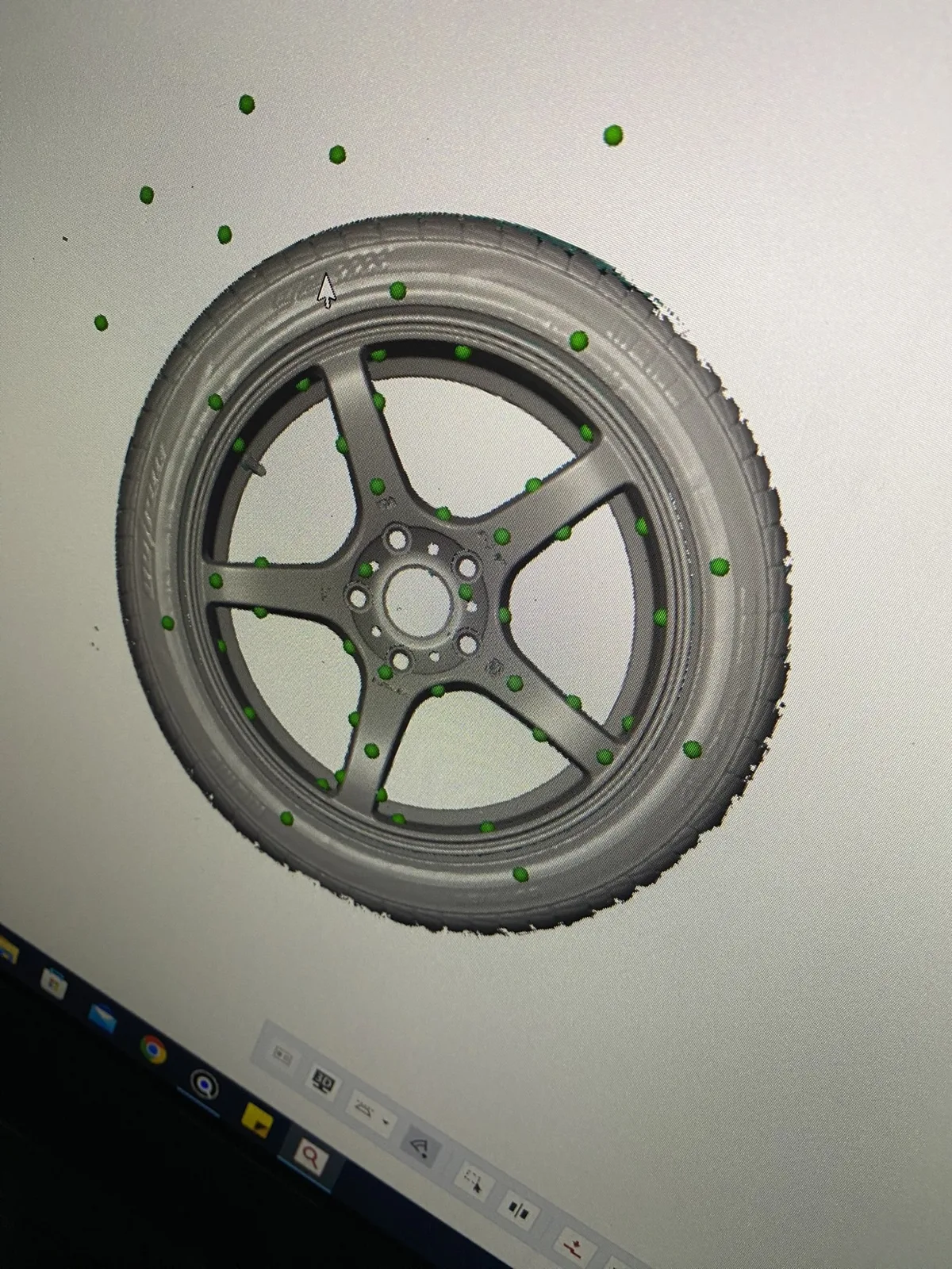
- Spread them irregularly, not in straight lines, and keep several in view at all times.
- Never move markers once the scan has started.
The Vertex3D kit includes 6 mm and 3 mm reflective markers. With markers, the scanner can align each pass even where the shiny surface itself gives little to lock on to.
Step 5: Use a light, removable matte spray only when needed
When a surface still gives holes (a chrome face, glass, a very dark glossy plastic), a thin matte spray turns it into a surface the scanner can read.
- Use a very thin, even coat. A thicker coat adds a layer to the surface, so keep it as thin as the surface allows.
- Spray only the problem faces, not the whole part.
- Use a removable spray and clean the part afterwards.
- Check that the part may be sprayed at all. Some parts, such as museum pieces, must not be touched, and for these the angle, marker and settings steps matter most.
- After scanning a sprayed part, check a known feature against a gauge or caliper to confirm the size is still right.
What does the Vertex3D solve, and what does it not?
| Surface | What should you expect on each surface? |
|---|---|
| Polished or shiny steel | Vertex3D and Vertex3D Pro scan these directly (maker and distributor statement). Test first; spray is rarely needed |
| Matte machined and cast metal | Usually easier; test first |
| Black or dark parts | Test first; exposure and angle changes and a thin spray on the worst faces may be needed |
| Chrome and mirror finish | Test first. May need markers on the surroundings, angle changes and a light spray |
| Transparent glass or clear plastic | The laser passes through or scatters; spray is normally needed |
| Very thin edges and deep narrow holes | A different scan mode may help; some features cannot be fully captured by a handheld scanner |
| Parts that must stay untouched (no spray) | Possible with markers, angle and scanner settings, with more time and some gaps expected |
No scanner removes every problem. A good result comes from the method, not only from the hardware. If a face cannot be captured cleanly, we say so, and measure that feature another way, for example with a CMM arm or a gauge. This note covers the Vertex3D and Vertex3D Pro; for the Vertex Tracker, ask us about your part.
How do we check a scan of a shiny part?
We do not rely on how smooth the picture looks. We compare the scan with the nominal CAD and show the deviation as a colour map with statistics, and we check known features against calipers, gauges or CMM values where they exist. Read the full method in 3D scanning vs CMM inspection or see our CMM inspection services in Coimbatore.
Where do shiny-part scans matter most?
Typical shiny, dark or mixed-surface parts include machined components, polished tooling, automotive trim and body panels, and cast parts with a machined face. See how these jobs are handled on our pages for 3D scanning services in India, reverse engineering services in India, how we rebuild a spare part that has no drawing and automotive reverse engineering. If you are choosing a scanner, how to choose a handheld 3D scanner in India compares the Vertex models, and the JINUOSH Vertex 3D scanner page has the full details. VShark is a distributor of JINUOSH. Need a printed copy or fit-check of a scanned part? See 3D printing from your 3D scan. For how a scan becomes an editable model, read scan to CAD in SolidWorks.