"How accurate is your scanner?" is the first question almost every customer asks. It's a good question, but the honest answer is: it depends on what you mean by accuracy, and on the part. Here's a plain-English guide to the numbers on scanner spec sheets and what they mean for your project.
Four numbers, four different things
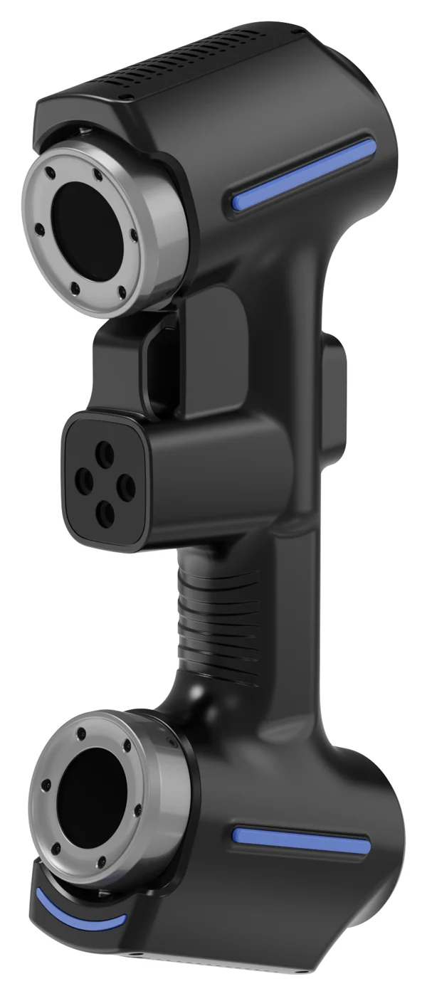
1. Precision (or accuracy) — e.g. 0.020 mm How closely the scanner measures a feature within a single, small measurement area. It's the best-case figure, often measured on calibrated artefacts. For example, the Vertex3D and Vertex3D Pro handheld scanners list 0.020 mm precision.
2. Volumetric accuracy — e.g. 0.015 mm + 0.035 mm/m How error grows as the part gets bigger. When you scan a large part, small errors add up as the scanner moves around it. The formula means a base accuracy plus an extra amount for every metre of part size. For a 2 m part, that example spec gives roughly 0.015 + (0.035 × 2) = 0.085 mm.
3. Volumetric accuracy with photogrammetry For large parts, a photogrammetry step first measures a framework of reference targets very accurately; the scan is then locked to that framework. This reduces error growth on big objects.
4. Resolution — e.g. 0.01 mm The smallest point spacing the scanner can capture. Higher resolution captures finer detail (text, knurling, small fillets), but resolution is not accuracy. A scan can be very detailed and still slightly out of size.
What affects real-world accuracy
Spec sheets describe ideal conditions. On real projects, accuracy also depends on:
- Part size: larger parts mean more accumulated error, unless photogrammetry or tracking is used
- Surface finish: shiny, dark or transparent surfaces scatter or absorb light; blue-laser scanners handle many of these well, and a light matte spray helps on the hardest cases
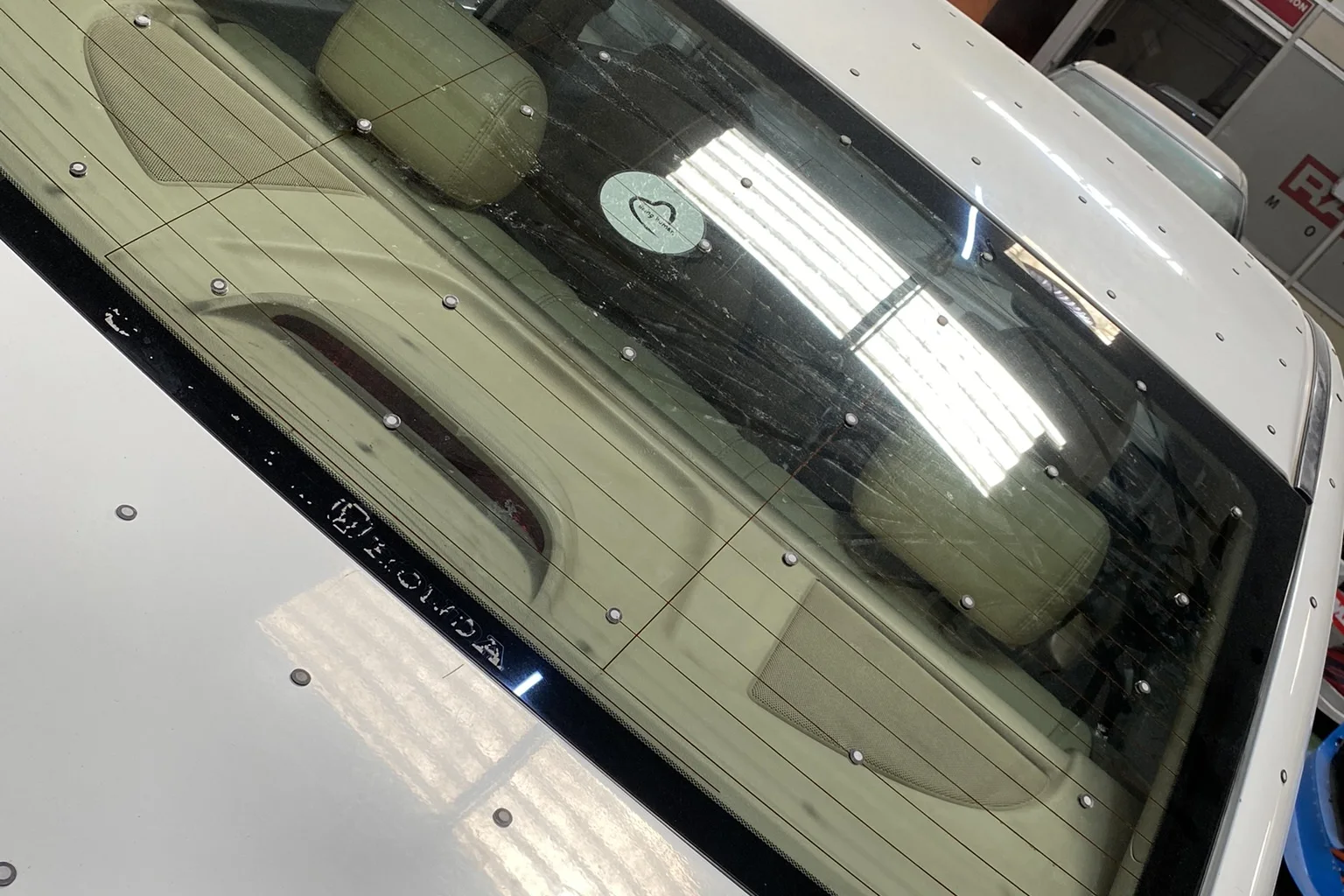
- Alignment and targets: good reference-marker placement keeps scans stable
- Temperature and stability: parts and scanners expand and contract; metrology work needs stable conditions
- Calibration: scanners should be calibrated regularly
- Operator skill: scan strategy matters as much as hardware
How we measure our own results
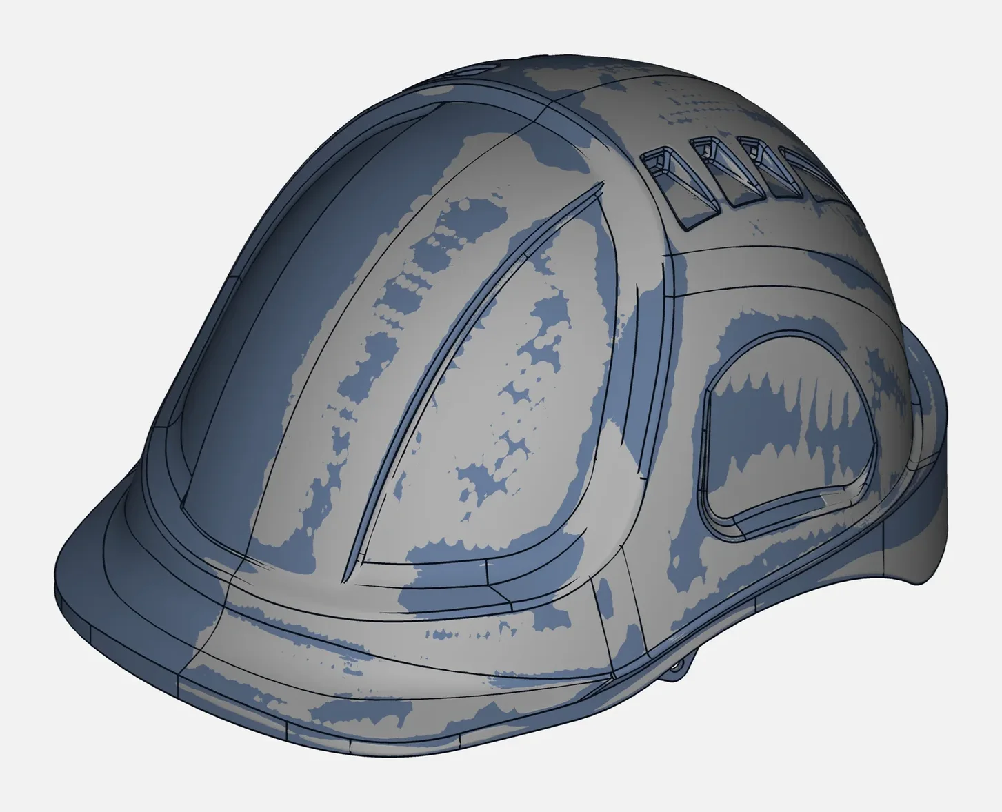
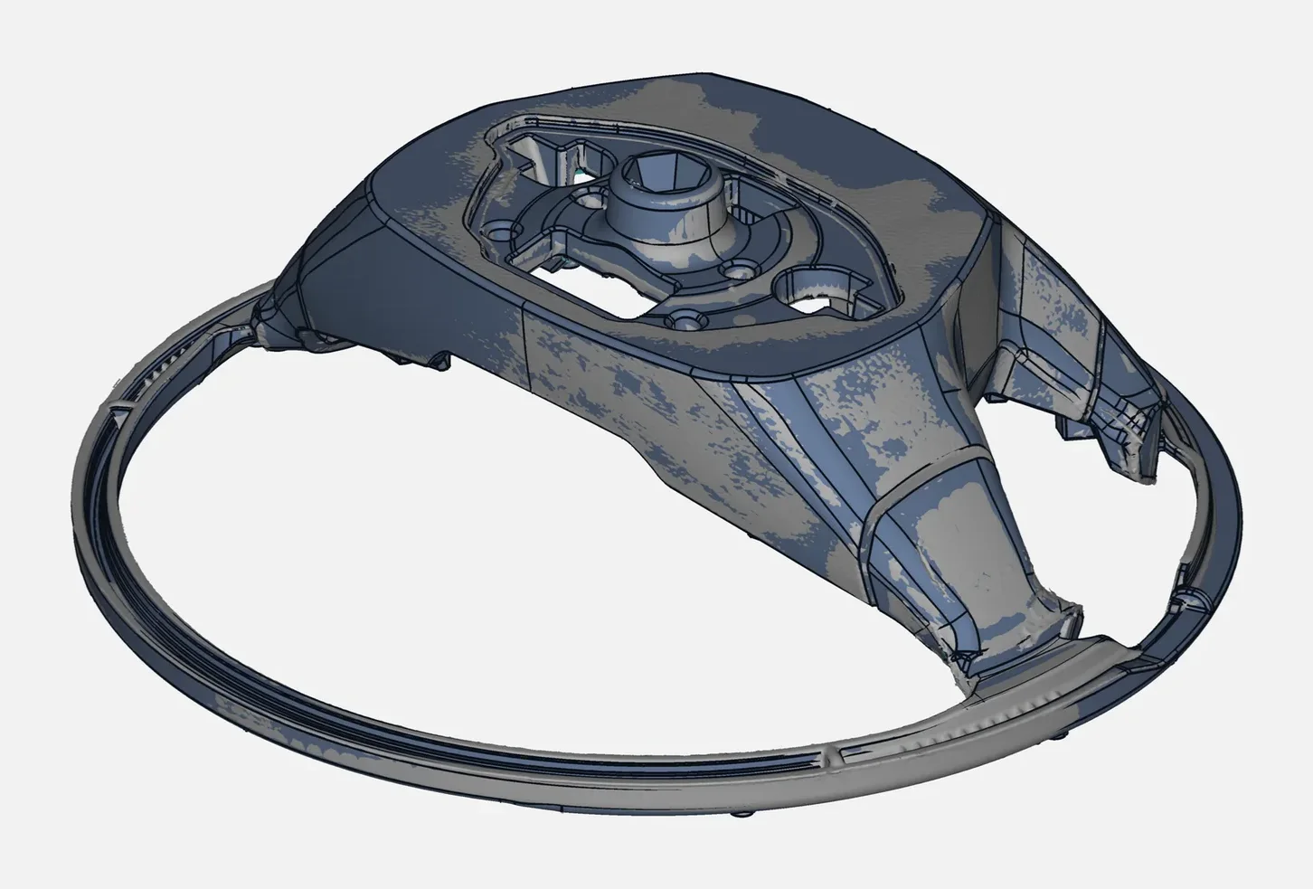
On every reverse engineering and inspection job we compare data in a measurable way:
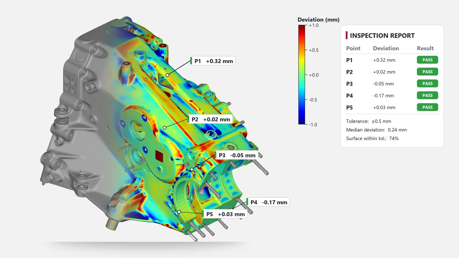
- Scan to CAD: the deviation between the final CAD and the scan, shown as a colour map and statistics
- Known features: checking measured features against calipers, gauges or CMM values where available
For example, on a cast transmission housing, the median deviation between scan and nominal CAD was about 0.24 mm. A figure like this is mostly casting variation in the part plus the chosen alignment, not scanner error, and it is exactly the kind of insight 3D inspection is meant to reveal.
Matching accuracy to your tolerance
A useful rule of thumb from metrology: your measurement system should be several times more accurate than the tolerance you're checking. A common target is a 1:10 ratio, though 1:4 to 1:5 is often accepted in practice.
| Your tolerance | Is handheld 3D scanning suitable? |
|---|---|
| ±0.5 mm (castings, mouldings, sheet metal) | Yes, comfortably |
| ±0.1 mm (machined parts, precision mouldings) | Usually, with a good setup |
| ±0.01–0.02 mm (bearing seats, precision fits) | Use a CMM for those features; scan the rest |
Ask the right question
Instead of "How accurate is the scanner?", ask: "Can you measure my part, at this size, to this tolerance, and show me the proof?" A good scanning partner will explain the setup and give you a report showing the result.
3D scanning in India and the UAE
VShark Solutions uses high-accuracy blue-laser scanning for reverse engineering and inspection, from Coimbatore and for clients across the UAE. Learn more about our 3D scanning service or digital metrology.